
RETURN TO M3W HOME PAGE
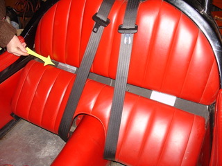
The upper seat backrest can now be slid down far enough to be pulled forwards at the bottom and removed.
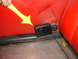
The knob on the handbrake lever just unscrews.
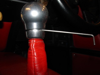
The gear knob has a ring on the bottom which unscrews to reveal three socket head grub screws which clamp on to a plastic sleeve. The screws are quite short so beware of undoing them too far and having them fall on the floor - they are a devil to find and stainless, so a magnet will not help.
The rest of the fixings are obvious.

Now remove the lower aluminium plate behind the seat back.
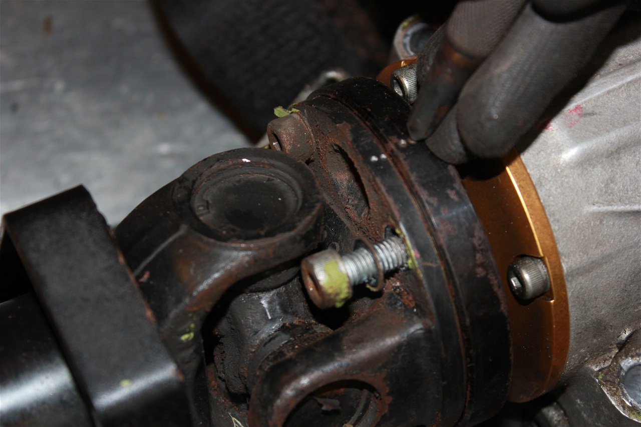
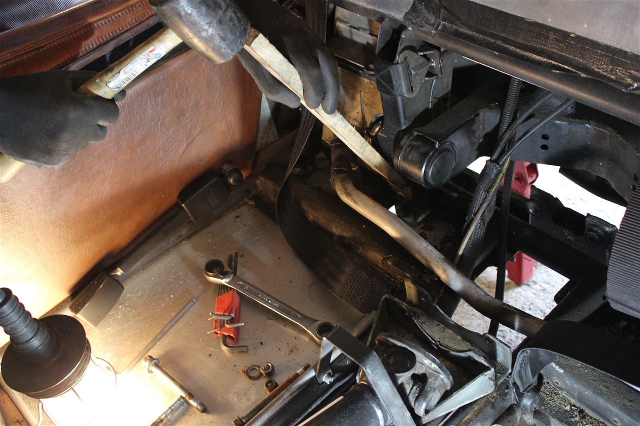
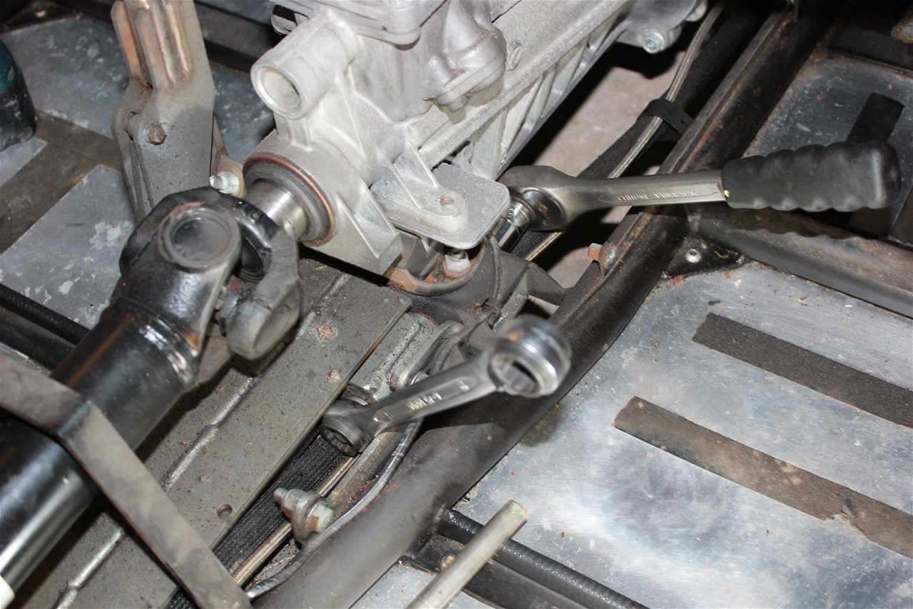
After marking the flanges for reassembly ( I doubt if the unit is balanced as an assembly "but just in case") remove the propshaft fixing bolts and telescope the shaft forwards out of the way.
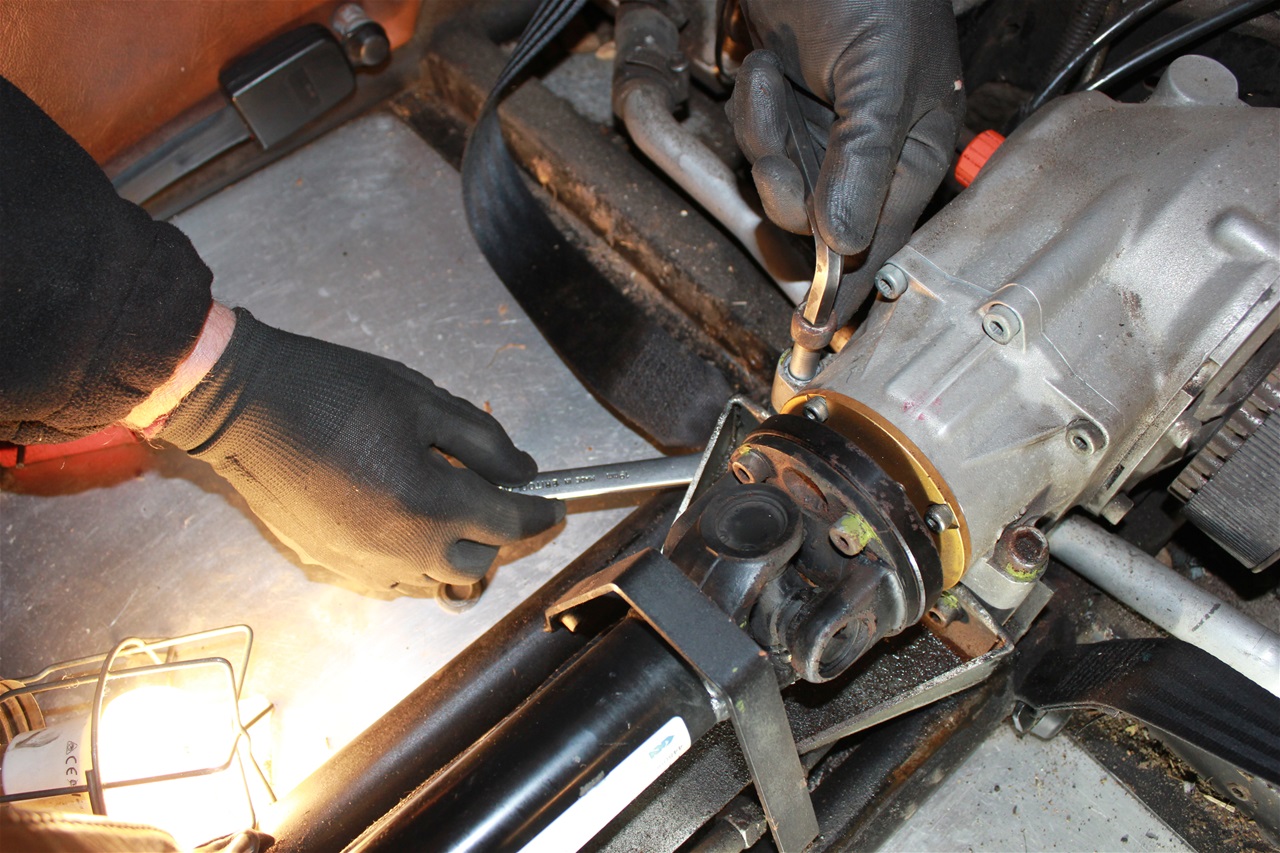
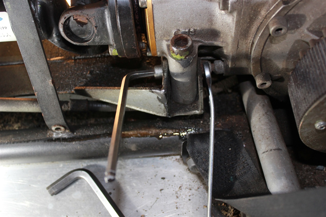
Remove the two M 12 fixing bolts at the back of the bevel box, the two M12 vertical fixing bolts at the front and also the two horizontal ones below the input flange.
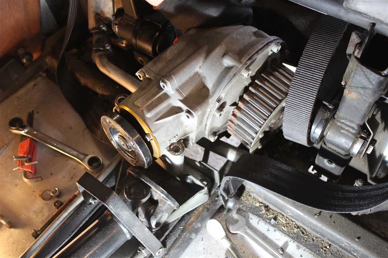
The bevel box will now lift out, it is quite heavy so stand inside the vehicle to help reduce strain on your back - ask an assistant to take it from you or have a suitable table to put it on, ready,
beside the vehicle. Don't remove the floor plate screws till this is done! Lift the front flange upward and replace the drive belt to one side, don't forget to reposition it when you put the box back in the vehicle before bolting it all down! The belt adjustment should be unaffected but check it before driving off for your first test run.
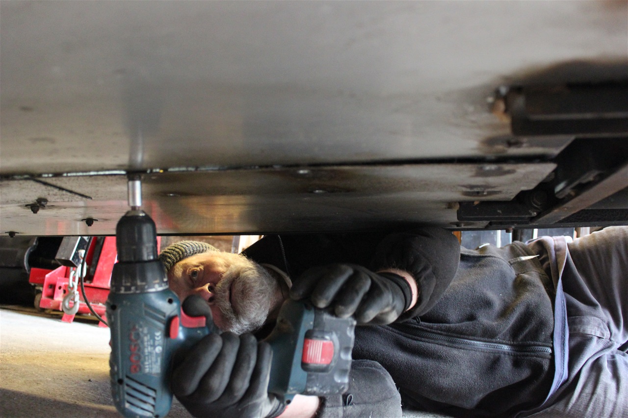
From below the vehicle remove the central aluminium floor plate.
While it is expedient to use a power tool for removal of these screws which are inserted in to riv nuts it is safer to put them back in by hand as the slightest problem with re-entering the thread or maybe a bit
of dirt in the thread and you will end up with the riv nut spinning round.
Also remove the bolts from the two side floor panels aft of the gearbox ( these are not fitted in all vehicles ), the main floor panels can remain in place but you have to flex them out of the way to fit the bottom half
of the front bevel box mounting.
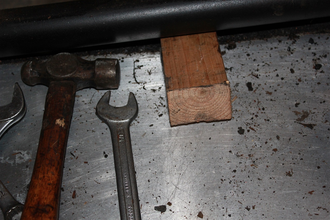
A couple of wooden wedges are most helpful to hold the floor panels down while you slide the bottom mounting in to place.
On later models you will find the adhesive mastic used to seal the plates to the chassis tubes very tough and you will need to use a lot of force and a sharp knife/chisel to cut through it.
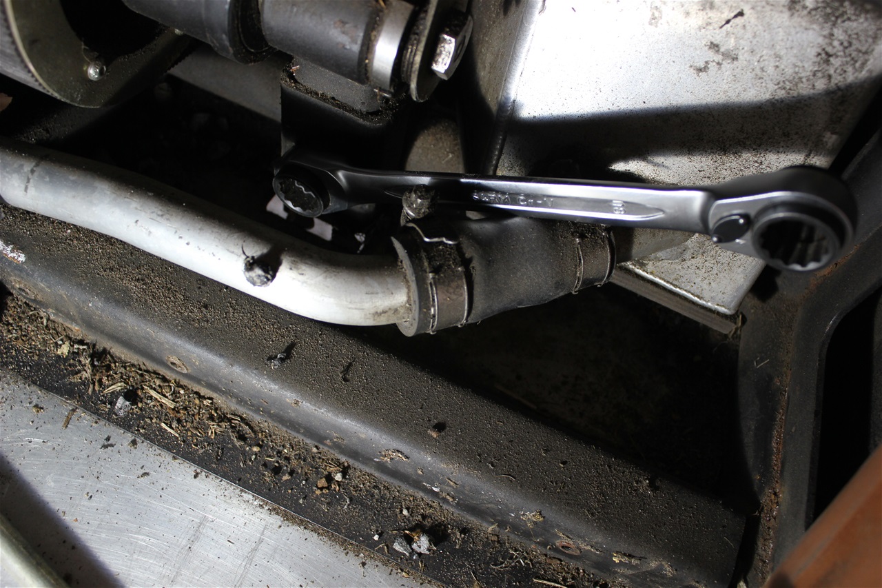
The rear cross member of the NVH kit can now be unbolted (7/16" x 4" use a 16mm spanner) from the chassis at each end and put it aside along with the bolts, you will not need them.
You may need to drive the NVH beam out with a wooden drift, work bit by bit equally at each end.
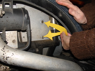
Go now to the front of the NVH front mounting beam and remove the two long bolts (7/16" x 6" use a 16mm spanner) which go through the silent bloc type bushes remove the NVH mount and put it aside. Replace the long bolts with the ones in the kit ( M10 x 80 socket cap heads with nyloc nuts and washers) and tighten them fully.
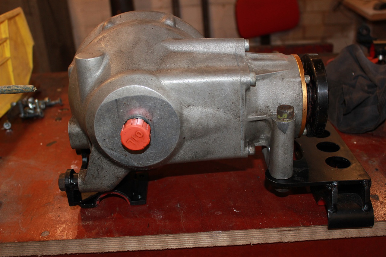
With the bevel box on the bench fit the top half of the front and rear rear mounts using the original bolts but only finger tight.
Slide the bottom clamp for the front mount in to place. This is best done from the rear of the floor panels which should be flexed down with wedges in place.
the floor plates will be pushed down permanently, where they contact the front mounting clamp, I find this is useful as the floor now drains when I get water inside while washing the vehicle.
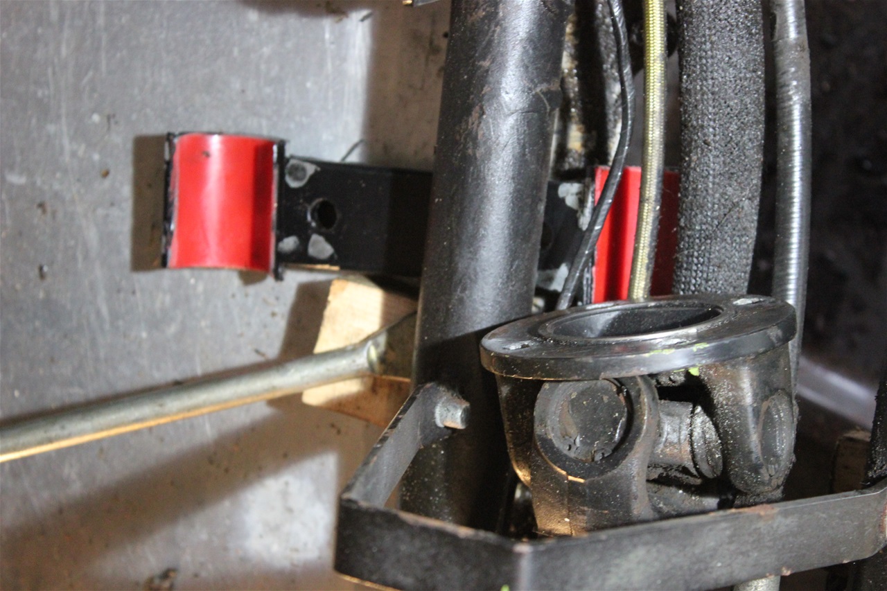
The clamps should be midway between the welds of the original mounting and those of the prop shaft guard. The bevel box can now be placed in position in the vehicle with the polyurethane lined clamp of the rear mount fitting snugly over the chassis tube. Re-fit the drive belt. Arrange the petrol pipes, handbrake cable, rear brake pipe and the electrical harness in the recess in the front clamp ( you might like to tape or clip them together in a bundle to help) . Now fit the bottom clamp of the rear mount in place from below leaving the bolts slack, use a drop of Loctite on each bolt. Slide the front mounting along the chassis tubes to allow the front clamp bolts to fit freely through, fit the nuts and washers loosely. The front and rear clamp bolts can now be tightened progressively in rotation to allow even seating of the polyurethane liners.
Be careful not to trap petrol pipes etc. in the clamp.
Then fully tighten the four bevel box mounting bolts, two at the back and two at the front.
Torque wrench settings for front mounting clamp bolts - M10 with dry threads and a new nyloc nut and plain washer 40 Newton metres ( 4 kg metres or 30 lbs feet )
Torque wrench settings for rear mounting clamp bolts M8 with Loctite and plain washer 30 Newton metres ( 3 kg metres or 22 lbs feet )
DO NOT be tempted to fit the top mounting in conjunction with the NVH kit. The three mountings in my kit must all be fitted together and the NVH kit fully removed.
The top mount can now be bolted in position using the M8 x 30 socket head bolts provided in the kit.
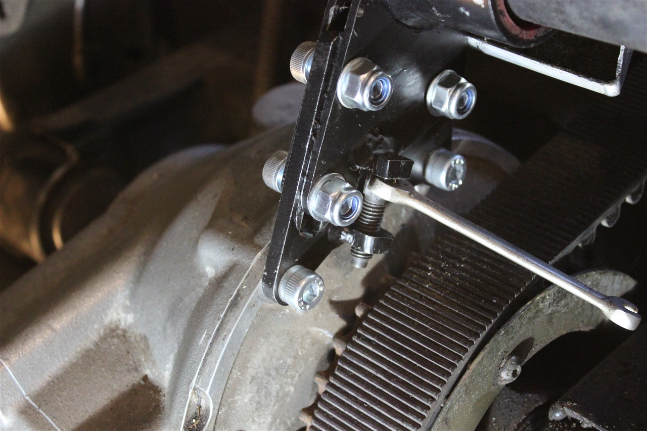
With the three clamp bolts loosely fitted, ( later versions of the kit only have two clamp bolts) wind up the jack screw, till all the slack is taken up in the top cradle and then tighten one half turn more.
Now tighten the three clamp bolts and the bevel box is fitted.
Replace the floor pan bolts, the prop shaft flange bolts ( lining up the marks ). Replace the trim panels and seats. Check the drive belt tension. Replace the parcel shelf.
You are ready for your first test drive - I know you will enjoy it! Pulling away and trickling along in dense traffic becomes easy. If your machine suffered from the banging on hard acceleration it will now be gone.
The common vibration experienced as the machine accelerates through 3,000 rpm will also be gone. Life becomes more bearable.