
RETURN TO M3W HOME PAGE
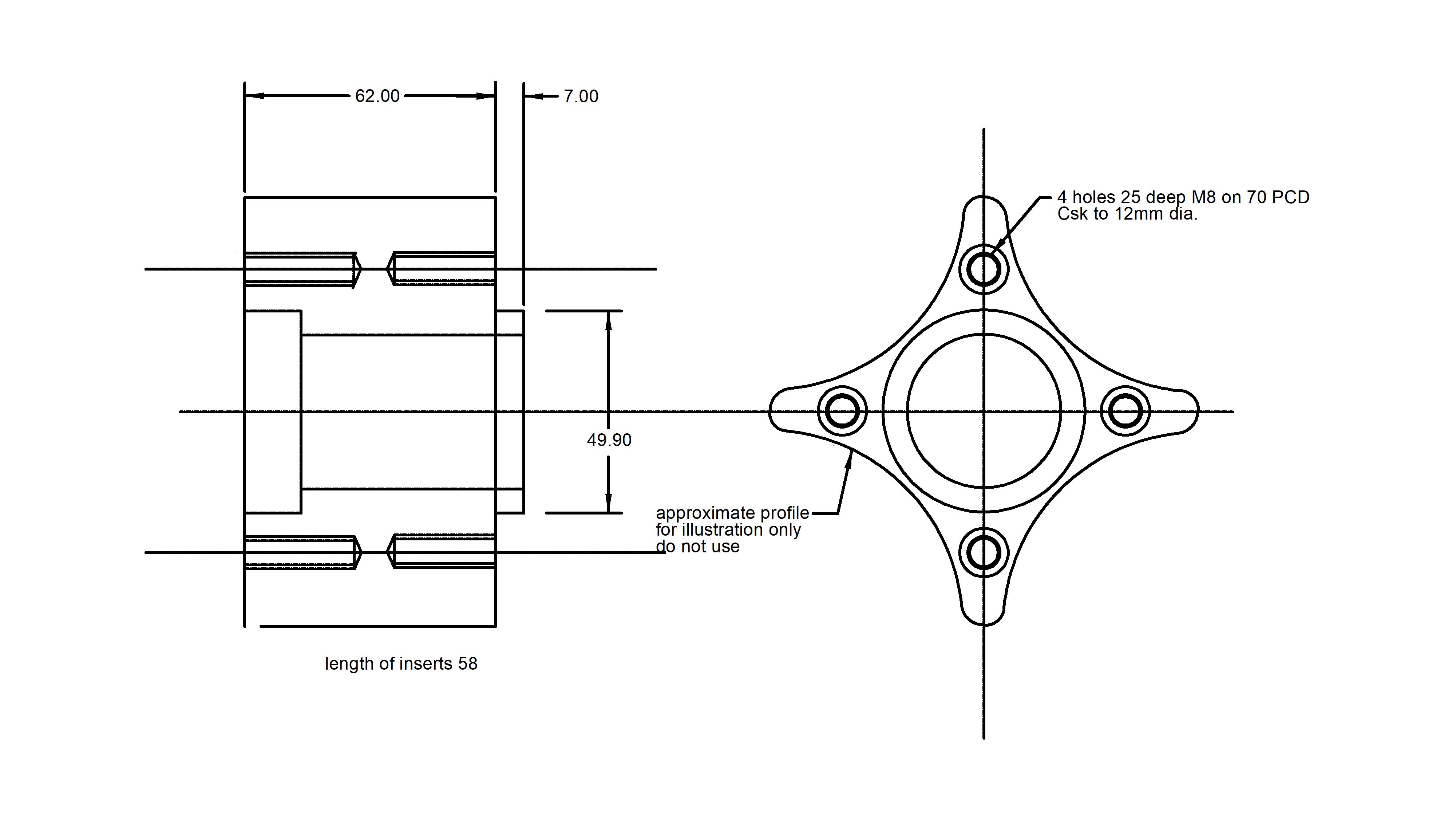
Drawing of modified inner rotor
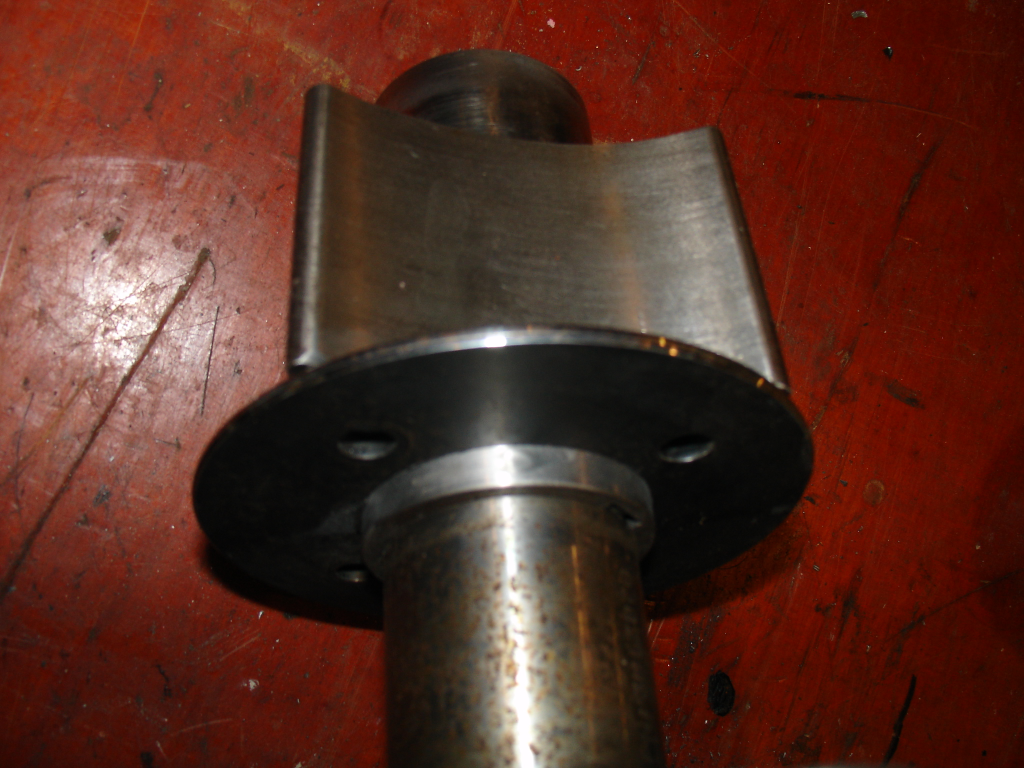
The inner rotor with the retaining plate in it's new position
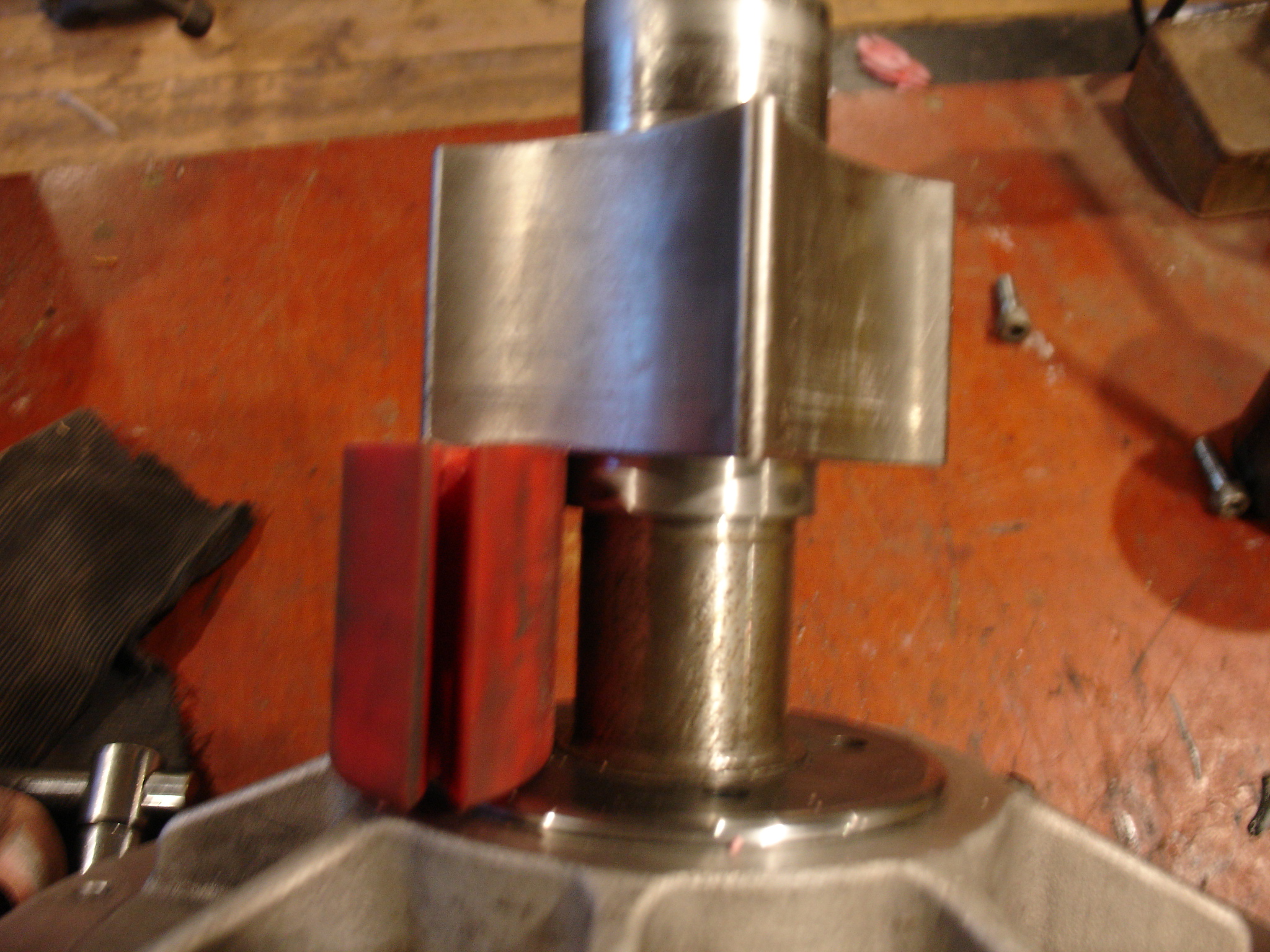
The inner rotor with the retaining plate withdrawn and an insert showing it's position ready to be removed
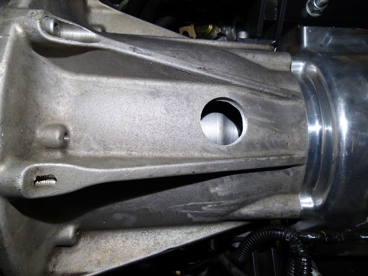
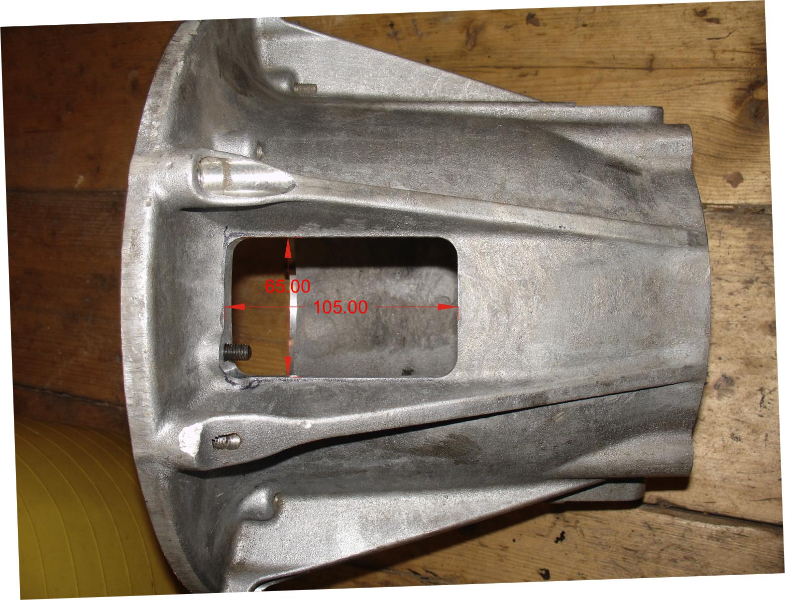
The modification requires this hole to be
enlarged and the dimensions are shown on the lower photograph above. The distance from the back edge of the cut out to the mating face of the bell housing is 27mm.
This can be done with the bell housing bolted to an angle plate on a large milling machine.
Alternatively if you wish to do it by hand then drill a hole approximately 20mm in dia at each corner and saw out the straight lines at the edge using a
reciprocating power saw. A domestic jig saw could be used, with care, from the inside of the housing. If you prefer, a line of small holes can be drilled
round the outline of the hole and this makes sawing easier. Most well equipped mechanics workshops will be able to carry this out. Be sure to smooth
off all edges as you will need to work through this hole to remove the inserts and cuts and grazes are best avoided. It is important to cut the hole as
close as you can to the webs on the housing, even then it will only just be wide enough for large hands..
This mod has to be carried out with the engine removed and so it should be scheduled in to coincide with clutch replacement, Centa insert replacement
or the installation of my upgrade kit.
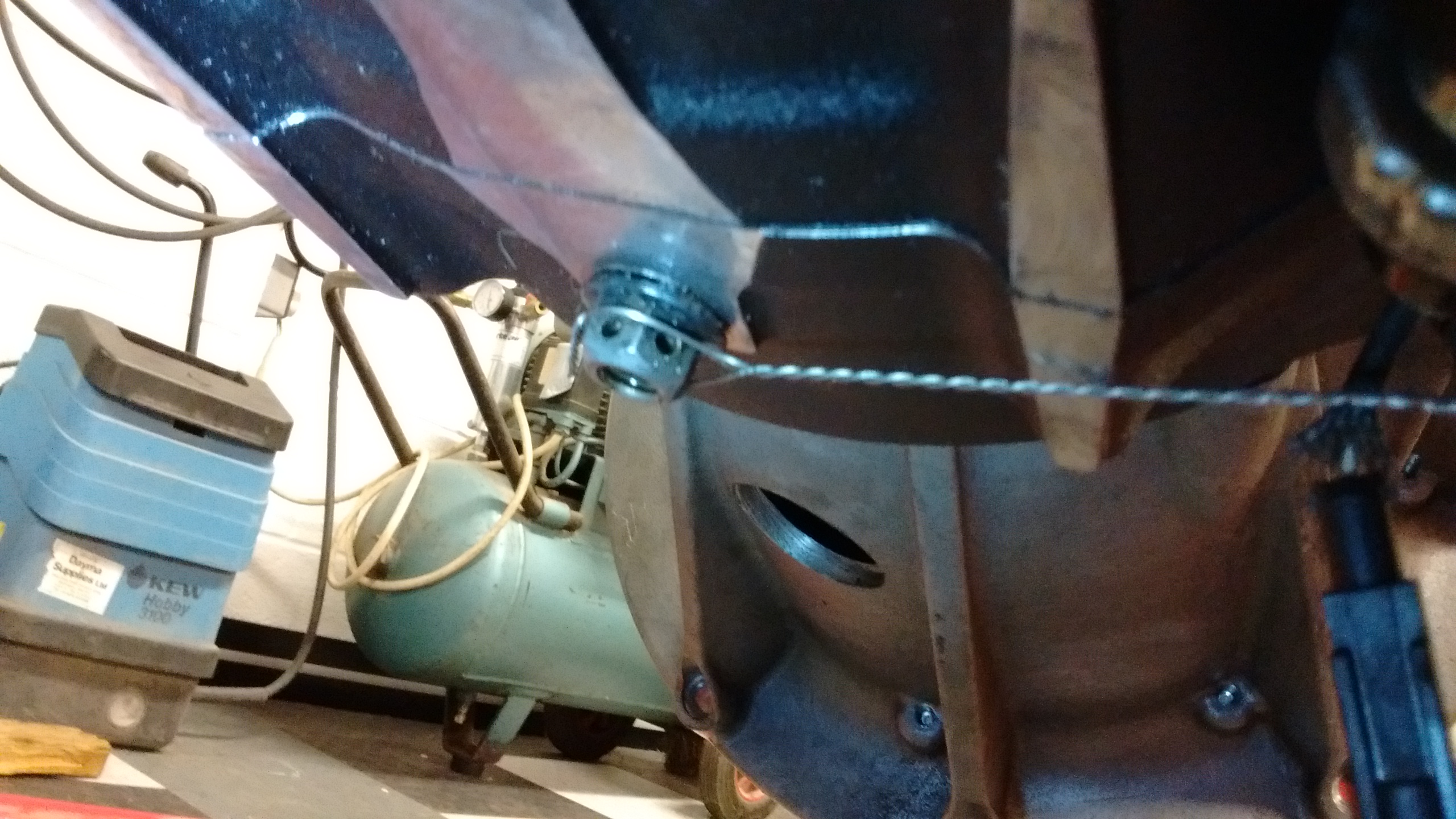
At the first sign of any deterioration of the inserts ie. excessive vibration and bits of brown polyurethane coming out of the hole under the bell housing, or as a preventative measure before a long run, or just as part of your routine maintenance schedule you should inspect or change the inserts.
Start by jacking up the vehicle and supporting it on some good axle stands. Alternatively run the vehicle on to a pair of ramps. Either way, high enough to work through the access hole under the bell housing. Remove both sparking plugs and cover the holes with a rag to safeguard against any foreign matter falling in.
Using the 1/4 inch drive hexagon bit driver with a 6 mm bit inserted and a 1/4 inch hex extension handle in place - these were supplied with your kit - loosen the first accessible cap screw holding the retaining plate in position, a good blow with the side of your fist on the extension handle should do the trick - re tighten them in the same manner. With two fingers or finger and thumb if your hands are small enough remove the screw and place it somewhere clean - it is important not to get any contaminants such as grit or grease on the threads - this makes the job of removal much harder especially if the contaminant is transferred to the female threads in the rotor. Then, using the same tool inserted in one of the four dummy cap head screws in the outer rim of the aluminium rotor, turn the engine clockwise ( viewed from the rear of the vehicle ) till you can reach and loosen the next retaining plate screw - continue till all four screws have been removed.
Slide the retaining plate back till it registers on the rearmost, larger diameter, part of the shaft. The insert at the bottom can now be removed using a thin screwdriver or something similar in the hole in the extraction lug and inspected for wear or cracking - replacing if necessary. Move on to each insert in turn - do not take them all out at once or you will have difficulty in re aligning the rotors.
When you are happy with the condition of the inserts - inspected and replaced or changed for new, slide the retaining plate back in to position and ( this is the tricky bit ) line up the lowest bolt hole with a threaded hole in the rotor. An Allen key can be used to poke in the hole and jiggle it all about till they line up. Now, again with two fingers, enter one of the cap screws and screw no more than finger tight. Move around till all four are just finger tight and the go round again tightening each screw in turn with a blow to the extension handle with the side of your hand - this is tight enough - they do not come undone on their own and you will want to be able to undo them again next time without too much force. If more force is needed to loosen a screw then jack the rear wheel off the ground (to prevent the possibility of your driving the vehicle of the axle stands! ), apply the hand brake and engage a gear - this will give you some resistance to your loosening effort.
Finally, drop the vehicle back to the ground and check the workshop clock - less than an hours work compared to an engine out exercise on an unmodified vehicle - well done!